
Welcome:
Login
|
Sign Up
|
About CircleID
Follow:
|
|
|

|
||
|
||
Some 50 years ago, at the Palo Alto Research Centre of that renowned photocopier company Xerox, a revolutionary approach to local digital networks was born. On the 22nd of May 1973, Bob Metcalf authored a memo that described “X-Wire,” a 3Mbps common bus office network system developed at Xerox’s Palo Alto Research Center (PARC). There are very few networking technologies from the early 70s that have proved to be so resilient (TCP/IP is the only other major networking technology from that era that I can recall), so it’s worth looking at Ethernet a little closer in order to see why it has enjoyed such an unusual longevity.
Hang on, was that 3Mbps? True, the initial Ethernet specification passed data at a rate of 2.94Mbps, not 10Mbps. That came later, as did the subsequent refinements to the Ethernet technology that allowed data transfer rates of 100Mbps, 1Gbps, and then 100Gbps. Terabit Ethernet, or TbE, is on the way, by all accounts. Why has Ethernet endured as a ubiquitous data framing protocol over all these years? What was the difference between Ethernet and a variety of other emerging technologies for local area networking, such as Token Ring, FDDI or DQDB? Why didn’t we adopt simple HDLC serial framing? What’s so special about Ethernet?
The first question to ask is: Has Ethernet really endured? Well, not really. You couldn’t take a piece of 75-ohm coaxial cable from the 1970s, increase the speed of the clocks in the electronics and run a common bus local area network using a data clocking rate of 200Gps. That just won’t work. So today’s high-speed ethernet networks have some bits in common with the earlier Ethernet networks, and some are radically different. However, it is still possible to take an ethernet packet frame off a high-speed Ethernet network and pass it into a 10Mbps Ethernet LAN. The Ethernet packet framing protocol and the station addressing plan are both largely unchanged.
Perhaps we should start this look at Ethernet from the perspective of 50 years ago and look at why Ethernet was so interesting for computer communications. There is an intriguing mix of simplicity and ingenuity within the original Ethernet design. On the one hand, it was surprising what Ethernet did not do: there was no explicit acknowledgment of the successful receipt of a packet nor any indication of any form of network failure, such as network segmentation. There was no consistent network ‘clock’ to impose a common time regimen upon the stream of digital pulses, nor any form of imposition of fair sharing of the common network to competing demands, which was at the time a conventional expectation for any shared communications medium. Nor was there any level of predictability within the system. Individual transmissions might wait for an indeterminate time before they could transmit, which means that there was the potential for network-imposed jitter. There was no flow control or any form of prioritization. The Ethernet design was not full duplex. Every transmission was heard by all attached devices. On the other hand, even though there was no overarching network controller within the Ethernet architecture, the common bus Ethernet model at that time was surprisingly effective at congestion management and was possible to achieve sustained Ethernet loads of over 90% of the total rated capacity.
At the time, in the 1970s, most packet-switched networks used point-to-point serial lines and used a basic framing format to wrap the payload packets. The preamble might contain some address field and a control code to indicate the role of the packet (such as control, information, or data) and possibly a length field. The packet would normally have a checksum attached and some kind of end-of-frame marker. There was no need to attach addresses to this media-level packet framing, given that in a point-to-point link, there was only one possible destination for the packet on the wire, namely the other end! However, with the shift in the computing environment away from large central mainframe computers towards a clustered environment of smaller computers linked by a common network, there was also an opportunity to introduce a multi-client network technology that allowed a collection of computers to communicate between themselves without the need for a single central controller to mediate these communications. Ethernet applied a design approach of a common shared bus to this space. Each client connected to a common medium and could then communicate directly with any or all other connected clients.
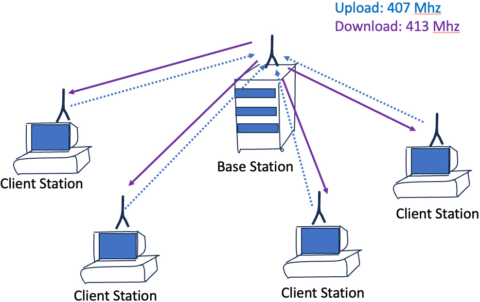
Of course, the design of Ethernet didn’t appear out of nowhere. The influential predecessor was a radio network developed at the University of Hawaii in the late 1960s, ALOHAnet. The original service objective of ALOHAnet was a low-cost radio network that connected remote users to a central mainframe computer. It used a hub-and-spoke model where the hub broadcast data packets over the radio to send to all clients on a single outbound channel on which all clients listened, and the hub listened to all clients on a separate single inbound channel (Figure 1). If the hub correctly received a packet, then it sent a short acknowledgment packet (again on the outbound common broadcast channel). The client behaviour was to send a packet on the inbound channel and wait for an acknowledgment. If an acknowledgment was not received by a client after a short wait interval, it would attempt retransmission. To avoid various forms of congestion-related deadlock, the retransmission process entailed a further delay by waiting for a randomly selected time interval. This acknowledgment mechanism was used to detect and correct for collisions created when two client machines both attempted to send a packet at the same time on the same common inbound radio channel. As this was a multi-host network, each attached client was given a unique address, and each packet included the address of the intended recipient.
Ethernet took this two-channel radio behaviour and mapped it to only a common piece of cable or a bus. Each attached client machine could transmit on this common bus, and all other clients would hear the transmission. The Ethernet design had removed the hub from ALOHAnet and allowed any client to send a packet directly to any other attached client (or all clients, using a broadcast address). Ethernet was an instance of a distributed access system.
The installation and operation of an Ethernet were extremely simple: A single segment of 75-ohm coaxial cable was unrolled around the office environment, passing nearby various workstation client computers. The specifications allowed for a cable segment of up to 500m and three such segments could be linked by repeaters, allowing a total cable length of 1.5km. Workstation clients attached to the cable by an Ethernet Transciever, which uses a so-called vampire tap to connect to the inner conductor of the coaxial cable and a control unit to process the analogue signal on the cable to digital signals to be passed back to the client workstation (Figure 2).
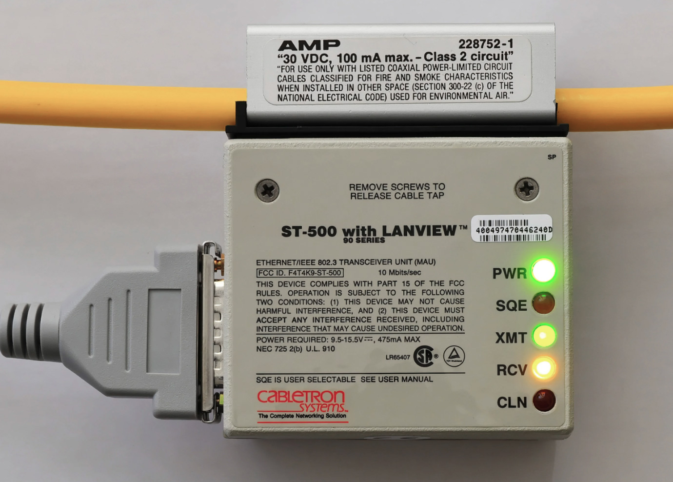
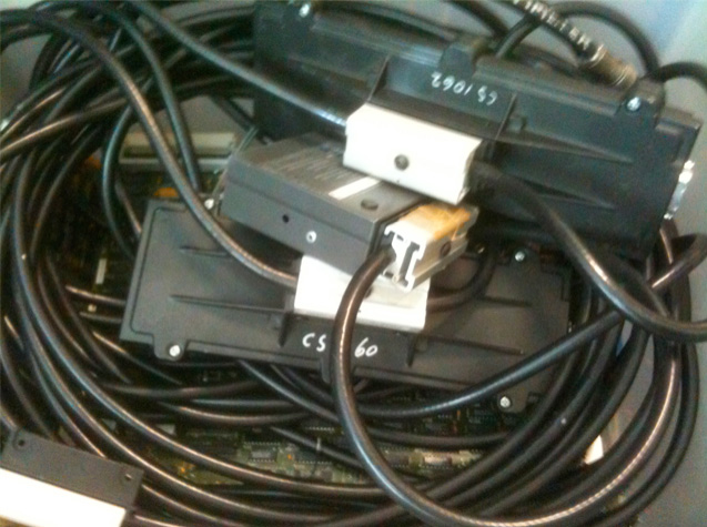
The thing about Ethernet was that it was ridiculously easy to perform your own Ethernet cable taps, and in the days before structured cable racks and neat ties, the sub-floor space in computer rooms where the coaxial Ethernet cable was conveniently bundled out of sight, the picture was a little messier than what the promotional photo is depicting. The reality under the false floor of the computer room typically ¬looked a lot more like this:
So, where’s the magic here? The best place to start answering this question is by looking at the second generation of the technology, the 1980 Ethernet specification, published by Digital Equipment Corporation, Intel and Xerox (DIX), which was a refinement of the earlier Xerox work.
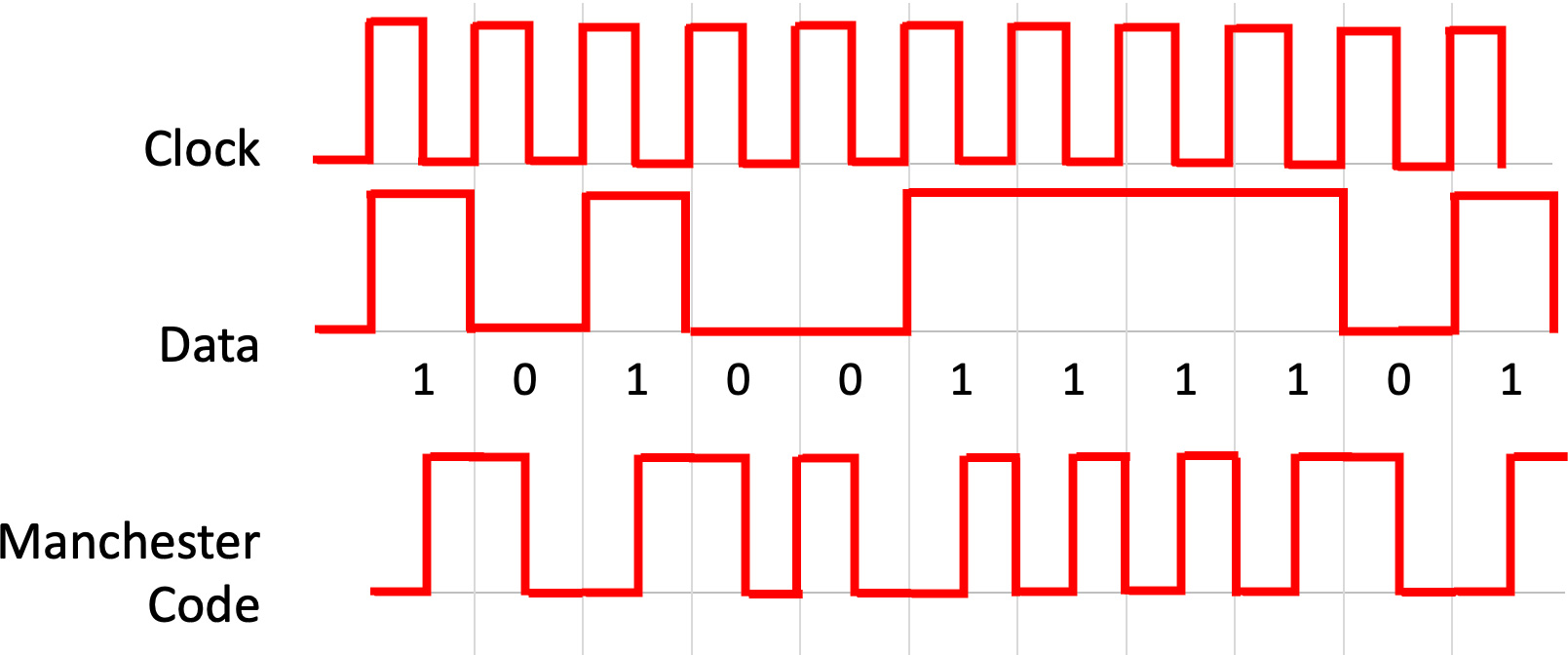
In looking at an Ethernet frame, firstly, and perhaps surprisingly for a high-speed system, Ethernet is asynchronous. The common wire does not provide a constant clocking signal that serves as the substrate for clocked data. Each transceiver operates its own autonomous data clock. The Ethernet frame starts with an enforced idle time of 96-bit times (or 9.6 µseconds), followed by a 64 bit preamble. The preamble is an alternating pattern of 1 0 1 0 ... terminating with two 1’s in bits 63 and 64. The purpose of the preamble is simple: it sets the clocking rate for the subsequent data packet. Every client’s task is to look for activity on the wire and synchronize its local oscillator against the implicit clock signal being received in the preamble. Once the receiver’s oscillator is in sync with the data, it only has to stay in sync for a further 1,518 bytes, or 12,144 bits, or just a little over one millisecond at 10Mbps.
Ethernet used Manchester encoding, where a logical 0 is represented by a high-to-low signal transition, and a logic 1 is represented by a low-to-high transition. All 1s would or all 0’s would correspond to a 20Mhz square wave (Figure 3). There’s no doubt that making a 20Mhz clock stable for 1 millisecond is a somewhat cheaper and easier task than making a clock stable for some years!
Well, no, not really, The Ethernet specification allowed for individual Ethernet frame payloads to be between 46 and 1500 bytes (Figure 4). A minimal IPv4 TCP/IP Acknowledgement packet is 40 bytes, which fits comfortably into an Ethernet frame, while a 1500-byte frame carries a 24-byte overhead or 1.57% media overhead. Even when you allow for the 9.6 µsecond interframe gap, the media overhead for maximum-sized Ethernet packets is still a very reasonable 2.3%.
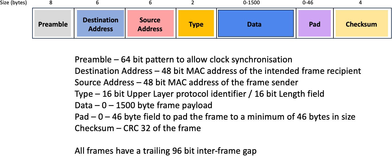
The outcome of this variable-sized packet encoding is the ability to maximize efficiency of the media layer, allowing both small and large packets to be carried without excessive overhead and without excessive payload padding.
The cost of variable-sized packets is increased potential for network-induced jitter, where a clocked real-time stream of data may have its timing altered as it passes through an Ethernet network. In a single-channel medium with mixed packet sizes, small packets have to wait for any preceding large packets to complete. There is no orderly queue in Ethernet. If a client cannot send a packet immediately, there is no scheduling queue to maintain any form of order between contending clients. Each client backs off for a random wait time.
There is a trade-off between data timing and network utilization, and, like TCP itself, Ether opted to head down the path of producing maximal efficiency rather than sacrificing speed and capacity for the sake of preserving implicit data timing integrity. In retrospect, it proved to be an astute design decision.
There is also an ingenious relationship between the minimum packet size and the Ethernet algorithm. The one thing Ethernet attempted to maintain was the property that a transmitter is always aware if another transmitter was active at the same time. Hence a packet must be big enough that the leading bit of the packet must be able to propagate to the other end of the Ethernet LAN, and the collision with the leading edge of another transmitter must propagate back to the original transmitter before the transmission ceases. That implies that the total end-to-end length of the LAN must be one-half the minimum frame size. You can make the minimum frame size smaller, but the maximal diameter of the LAN itself shrinks, or you can support physically longer LANs but at the expense of less efficient payloads because of a larger minimum frame size.
All this relates to the speed of electromagnetic propagation over a copper conductor, which in turn relates to the speed to light in a vacuum.
The speed of light in a vacuum, or the physical sciences constant c, is probably the most researched constant in all of science. According to electromagnetic theory, its value, when measured in a vacuum, should not depend on the wavelength of the radiation. According to Einstein’s prediction about the speed of propagation of light within the general theory of relativity, the measured speed of light does not depend on the observer’s frame of reference; the speed of light in a vacuum is a universal constant.
Estimates of the value of c have been undergoing refinement since 1638 when Galileo’s estimate of “If not instantaneous, it is extraordinarily rapid” was published in “Two New Sciences.” The currently accepted value is 299,792.458 kilometers per second.
The speed of light in glass or fiber-optic cable is significantly slower, at approximately 194,865 kilometers per second.
The speed of propagation of electrical charge through a conductor is a related value; it, too, has been the subject of intense experimentation. Perhaps the most bizarre experiment was conducted in Paris, in April 1746, by Jean-Antoine Nollet. Using a snaking line of some 200 monks connected by a mile-long iron wire, Nollet observed their reactions when he administered a powerful electric current through the wire. The simultaneous screams of the monks demonstrated that, as far as Nollet could tell, voltage was transmitted through a conductor “instantaneously.”
Further experimentation has managed to refine this estimate, and the current value of the speed of voltage propagation in copper is 224,844 kilometers per second, slightly faster than the speed of light through a fiber-optic cable.
Relating this value back to the design of Ethernet, a 10Mbps system running over copper wire will carry bits at 0.75 the speed of light in a vacuum, or at 224,844 kilometers per second. This means that 576 bits at 10Mbps will be contained in 12,951 m of copper cable. The original Ethernet design specifications allowed for a total sequence of three 500m runs of copper cable, plus allowance for 2 repeaters, and a generous allowance for some level of physical misconfiguration!
The next piece of the Ethernet puzzle is the ingenious CSMA/CD algorithm (Carrier Sense Multiple Access/Collision Detection), which, as we’ve already noted, was derived from the ALOHAnet design. A transmitter first waits for any current activity on the common bus wire to stop (Carrier Sense), and then it will wait for a further 9.6 µseconds (96 bits at 10Mbps) and then commence transmission of the frame, starting with the 64-bit preamble. While it is transmitting its frame, it monitors the medium to ensure that no other transmission is taking place.
If it detects another transmission during the sending of the frame (a collision), then the transmitter sends a jam signal for another 32-bit times (3.2 µseconds). The jam signal will also cause all other clients to receive a corrupted ethernet frame, and the checksum calculation will fail, and the packet will be discarded.
After sending the jam signal, the sender then aborts the transmission and backs off for an interval before trying again with the initial carrier sense step. The backoff interval is a multiple of a slot time (where a slot time is 51.2 µseconds, which is the equivalent of the time to transmit 64 bytes, which is minimum sized Ethernet packet (less the preamble bits)
The backoff interval is a calculated as a random number r where 0 ≤ r < 2k, and where k = MIN(n,10), where n is the frame’s collision counter. Thus, if a transmitter encounters a collision for the first time, if will back off between 0 and 1 slot times (0 to 51.2 µseconds). If this results in a second collision, then it will back off for a time of between 0 to 3 slot times (0 to 153.6 µseconds), and so on until the 10th collision for this frame gives a random wait interval of between 0 and 1,023 slot times. After the 16th blocked transmission attempt, the frame is discarded, and the MAC layer reports an error. (Any resemblance to the packing efficiency of hash array using exponentially spaced collision side chains is not a coincidence, and the packing outcomes for such hash tables and Ethernet are remarkably similar.) So how long could a frame wait before being sent on the media? The worst case is just under half a second.
Of course, the issue here is that the algorithm is fair in that, over time, all transmitters will have an equal probability of being able to transmit on the channel. There is no controller and no critical point of failure in a LAN, nor is any connected station reliant on the correct operation of any other connected station. Ethernet is indeed a peer network technology that operates in a plug and play fashion.
The next Ethernet innovation was in client addressing. A common technique for networks at that time was to use short (often just 8 bits in size) address fields and instruct the LAN administrator to configure each connected device with the next available address. That way, the address fields in the packet took up minimal space, increasing the network’s carriage efficiency. Ethernet took an entirely different approach, and Ethernet (as well as IEEE 802.3 MAC addresses) used a 48-bit address field. Each manufacturer is assigned a block of numbers and adds a locally unique suffix to create a globally unique mac address for each Ethernet device.
What comes shipped from the network interface manufacturer is an Ethernet device with a globally unique address. This allows the end user to simply plug the device into any LAN with the knowledge that there will be no local address clash. Not only did this approach of using unique MAC addresses make wired networks easier to set up, but it also proved remarkably useful in more dynamic connection contexts, such as wireless 801.11 WiFi networks, where devices can associate within a wireless service realm without causing havoc over clashing wireless addresses. It remains to be seen how long the 48-bit address field will last, but it has been pointed out that if you manufacture 2 billion Ethernet devices a day, it will take 385 years to run through this 48-bit address space!
From a technical perspective, Ethernet achieved an elegance in simplicity by avoiding over-engineering the technology. But it took more than that to achieve the level of ubiquity that Ethernet has enjoyed in the face of well-funded competition. The decision by Digital, Xerox and Intel to create an open standard for the 10Mbps Ethernet technology was a significant factor, enabling a large collection of vendors to build interoperable products. The consequent adoption of this standard by the IEEE 802 committee and the release of the IEEE 802.3 Ethernet LAN Standard took this industry alliance and pushed it firmly into the realm of an industry-wide standard. The consequent market competition ensured that products were keenly priced, and the wide range of vendors forced each vendor to strictly adhere to a common standard in order to ensure that their products inter-operated with others. The increasing volume of deployment also allowed manufacturers to achieve economies of scale, and at that point, Ethernet had it made—it was faster, simpler, and cheaper than anything else around for local networks.
Nothing stays stable for very long, and Ethernet moved on as well. The original Ethernet specification used thick coaxial cable and vampire tap transceivers that were pretty chunky, to say the least. By 1985 the IEEE standardized 10Base2, a wiring scheme that used thinner, more flexible coaxial wire. From there, Ethernet moved to standard office cabling systems, and the IEEE standardized Ethernet over twisted pair (10BaseT) in September 1990.
The copper twisted pair standard was also an outcome of a changing topology of Ethernet deployments. The original concept of Ethernet was a ‘snake’ coax cable passing close to each workstation, and the station would use a drop cable to attach to this common cable spine. But it was increasingly impossible to squeeze every client onto a single cable segment, and there was interest in both extension devices that allowed for larger Ethernet systems and interest in altering the underlying local topology to use the emerging office structured cabling systems that used a star hub twisted pair wiring approach. The next evolutionary step was to expand the network beyond its design limits. The problem was the careful interdependence between maximal cable paths, maximal propagation times and minimal packet sizes. With repeaters, it was possible to build larger Ethernets, but collision detection was compromised if the length of the longest run was more than twice the minimum frame size. Upper-level reliable transport protocols, such as TCP, could repair these issues of undetected packet collisions, but if the application was based on simple datagrams, then the packet drop could pass undetected. Applications such as DNS over UDP, undetected collisions forced a greater dependence on application-level timers and significantly slower performance.
The response was to segment the Ethernet network into a number of distinct collision realms. Bridges were perhaps the first real change to the original Ethernet concept, as a bridge does not pass on collisions. A bridge picks up Ethernet frames from one collision domain LAN, inspects the destination MAC address, and retransmits the frame on the other collision domain if the Mac address is known to be on the other domain. Bridges are essentially transparent devices, in that when two stations communicate across a bridge, there is no way that either station can discover that there is one or more intervening bridges. The packet format is unaltered by the bridge, and the bridge passes on all broadcast packets as well as all unicast packets.
Of course, the real giveaway sign of the use of a bridge is increased latency. As a bridge reassembles the entire packet before switching it onto another LAN, there will always be a minimum latency of the packet size between any two stations. Concerns about the extended latencies encountered in large LANS lead to the interesting concept of early switching, where the switching decision was taken as soon as the destination MAC address was received, and the remainder of the packet was switched through at the wire rate. If the source packet encounters a collision, the collision will need to be reproduced on the destination LAN where the packet was already being transmitted.
From this 2-port model comes the notion of a multi-port bridge, and in a multi-port bridge, it’s possible to use an internal switching fabric that allows multiple packets to be switched between LAN interfaces in one switching cycle. This is the core of the LAN switch, where a number of individual LAN ports are interconnected via a switching fabric.
The other development was the introduction of the full-duplex Ethernet architecture. This is still an Ethernet LAN, but in this case, there are only two stations. There are also two distinct communications channels, one allowing the first station to send frames to the second and the other to allow frames to be sent in the opposite direction. Now one station’s transmissions do not interfere with the other, and there is now no LAN length restriction due to the need to enforce a collision restriction. Using this approach, it is possible to interconnect two LANs using a wide area serial link between two bridges, and arbitrarily complex topologies of LAN interconnections can be constructed. This collision-free full duplex architecture has been a cornerstone in extending the speed of Ethernet.
But Ethernet is a very simple framing architecture, and the problem with setting up complex topologies is that it’s way too easy to set up various forms of loops. The Ethernet Spanning Tree protocol was a way to extend the “plug-and-play” approach to complex bridged Ethernet topologies that allowed various forms of automated detection of link redundancy and failover from primary to secondary paths.
In the pressure to increase the range, speed and capacity of Ethernet, the architecture of reliability in packet transmission has been questioned. The design of the common bus architecture was intended to provide the sender with some level of assurance that the medium had delivered the packet to the intended receiver. What it did not do was to provide any indication to the sender that the packet was processed by the receiver, that it was successfully passed to the receiving process.
If the concept of reliability in packet delivery is important, then it is important to appreciate that the common bus CSMA/CD Ethernet cannot deliver all aspects of reliable packet delivery. If an application wants reliable data service, then it needs to use a reliable transport service, such as TCP. In general, it’s a role of the upper layers of the protocol stack to provide reliable delivery service if that is what is desired by the application. In which case, what’s the point of Ethernet’s efforts to offer some partial reliability? If the entire intent of the collision avoidance measures was to increase the efficiency of the medium when using a common bus, then if you moved away from a common bus, then did it make sense to do anything at all in terms of media level reliability? The answer to that question is “no”!
The next evolution of Ethernet occurred in the early 1990s with the introduction of 100Mbps Ethernet. With the speed change came a change to the basic concept of how LANS are constructed. Remember that in the basic CSMA/CD common bus architecture of 10Mbps Ethernet, the maximum diameter of the LAN is half the size of the minimum packet. That is, if a transmitter is sending a minimum-sized packet, and at the other end of the LAN, a transmitter also commences to send the instant before the leading bit of the original transmission reaches the new transmitter, then the collision response must reach the original sender before the entire packet is placed onto the wire. But if we up the speed by a factor of 10 and leave everything else the same, then LANS will shrink from a maximum diameter of 1,500m for a collision domain to around 150m.
Of course, the other option is to increase the minimum and maximum packet sizes by a factor of 10, but this would represent a relatively inefficient trade-off with many transport protocols, as well as having to implement some media-level frame fragmentation features to allow a large frame to be fragmented into a set of smaller frames if you want to interconnect a 100Mbps system to a 10Mbps system. The Ethernet design for 100Mbps started off with the objective of keeping a consistent packet format and packet size range and allowing all other parameters to adjust. While, in theory, this forces a common bus 100Mbps Ethernet into a relatively small maximum diameter, 100Mbps, has been used with various forms of switching hubs, allowing a twisted pair run of 100m from the hub point to the station. With this speed step, we moved away from a single common bus and a collision framework into a set of serial links and Ethernet switches. We replaced the coax cable snake with hub and spoke structured wiring, which remain with us through to today.
The next step was to a 1 Gigabit data rate, and again the frame size range of 46 to 1500 bytes of data was preserved. Like the 10 and 100Mbps Ethernet specifications, a point-to-point connection can operate in either half-duplex or full-duplex mode. The half-duplex mode of operation was problematic at this speed, as the network extent is reduced to some 15m at this speed, so the half-duplex version of Gigabit Ethernet supports carrier extension, where the slot time is extended by a factor of 8 to 4096-bit times. Coupled with this is the extension of frame bursting, allowing multiple short frames to be packed into a single contention interval in half-duplex mode. Full duplex gigabit Ethernet does not need such modifications and operates with the same 96-bit inter-frame spacing, the same Ethernet frame size range and the same frame format as the original 10Mbps CSMA/CD common bus Ethernet.
And then came 10 Gigabit Ethernet. With this standard, the entire concept of half-duplex operation has been dropped, and with it, any remnant of CSMA/CD. The 10G Ethernet specification originally applied to full-duplex mode over fibre optic cables. There is no preamble to a frame at these rates, and instead, the link uses a carrier signal to keep the sender and receiver in sync. The industry stabilized on 10 Gigabit Ethernet systems from the mid-1990s for the next 15 years. It reflected a slightly slower evolutionary path for increasing the data speeds in optical signal transmission systems and a somewhat lower level of intensity of customer interest in a significantly faster network performance at this time.
The work on specifications of ever-faster Ethernet was not concentrated on changes to the Ethernet framing or access specification. The frame sizes were unaltered, as were most other aspects of Ethernet. This looked a lot like 10GE with a faster data clock. The concentration of effort was around the modulation of the photonic signal. Up to 10Gbs, it was possible to use simple on/off encoding and achieve acceptable transmission length over single-mode fibre cable. However, to lift the speed, the optical designers turned to group coding, making use of phase shift keying, and also to amplitude coding, similar to the earlier work on improving the speed of analogue modems in the telephone network. If the signal could be divided into 16 discrete points in the Fourier space, then each point corresponded to a selection of 1 in 16, or 4 bits. In effect, this allowed the optical designers to increase the number of bits per baud. The trade-offs here include target distance, optical power, fibre characteristics, so the effort was a balance of lifting the baud rate and increasing the number of discrete encoding points in Fourier space.
There are a number of offerings in the market for 200GE and 400GE systems, and the standards work is underway in the IEEE for 800GE and 1.6TE. As with the earlier 10Ge to 100Ge transition, progress is expected to be paced rather than accelerated. The current level of pressing demand for such single-channel speeds exists at present only in the realm of the hyperscalers, such as Google, Facebook and Microsoft, while the larger mass of the industry is still coming to terms with a more gradual transition into the 100GE world. As we’ve seen in the evolution of fibre speeds, the critical path here sits within the evolution of digital signal processors (DSP), where the achievable silicon track width determines the level of complexity and sensitivity of the DSP chip. We can get into the Tbps space using a base baud rate of 190Gbd on a fibre system using PCS-144QAM signal coding and DSPs built on a chip track width of 5nm. This is still at the leading edge of technology capability.
The refinements of DSPs will continue, but we may see changes to the systems that inject the signal into the cable. In the same way that vectored DSL systems use pre-compensation of the injected signal in order to compensate for signal distortion in the copper loop, it may be possible to use pre-distortion in the laser drivers in order to achieve even higher performance from these fibre cable systems.
What’s left of Ethernet in this forthcoming Terabit bit incarnation? At this point, we’ve reintroduced constant clocking in terms of a carrier signal, we’ve dispensed with CSMA/CD and returned to a full-duplex mode of operation. We’ve kept the range of frame sizes, and we’ve retained the 48-bit unique MAC address framework in a largely unaltered Framing format. Perhaps we’re now down to the essential fundamentals of what makes a network design an instance of Ethernet. Despite what we may have thought at the time, Ethernet is not a CSMA/CD common bus Local Area Network. Ethernet has turned out to be no more and no less than a global addressing scheme for devices that share a common framing format to transmit data.
Any maybe that’s enough.
Happy Birthday Ethernet!
Sponsored byIPv4.Global

Sponsored byRadix

Sponsored byCSC
Sponsored byDNIB.com

Sponsored byVerisign

Sponsored byWhoisXML API

Sponsored byVerisign


A World-Renowned Source for Internet Developments. Serving Since 2002.